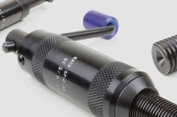
KATO® wire thread inserts are the insert of choice when it comes to enhancing the durability and strength of threaded joints. Whether you’re working on aerospace designs, automotive components or other precision engineering projects, understanding the correct installation procedure for these inserts is critical to ensuring optimal performance.
In this guide, we’ll walk you through the step-by-step process of installing KATO® wire thread inserts, whilst also highlighting key considerations that can affect the quality and longevity of your installation.
Step 1: Drill
The first step in the installation process is drilling the hole where the insert will be placed. The diameter of this hole, known as the minor diameter, is crucial. It needs to conform to standards like NASM33537 and MA1567 to ensure that it meets the required specifications after tapping and any subsequent treatments, such as anodising or chemical conversion coating.
- Drill size considerations: The recommended drill sizes are based on expected material behaviour, particularly for enhancing tap life in harder materials. However, real-world conditions may necessitate adjustments to these sizes. For example, if the material will be plated, you’ll need to account for plating tolerances to achieve the correct minor diameter after tapping.
- Hole depth: The depth of the drilled hole should be sufficient to accommodate the insert, the tap chamfer and provide chip clearance. The “F” dimension is a critical factor here; it represents the minimum full thread depth needed, plus allowances for the tap chamfer and set-down (the depth below the surface where the insert is installed). For example, for plug taps with a nominal diameter of 5/16” (or M8), the “F” dimension minimum allows for a male centre on the tap equal in length to half the nominal tap diameter.
Step 2: Countersink
Before tapping, it’s advisable to countersink the drilled hole. This step involves creating a slight conical recess at the start of the hole to prevent a feather edge, which can occur when the threads begin abruptly.
The standard practice is to countersink at an angle of 120º ± 5º to the specified “M” diameter. This angle matches the thread’s angle, the insert’s cross-section, and the tip of the inserting tool’s prewinder. This alignment ensures smooth and efficient production installations, making the entire process faster and more reliable.
Step 3: Tap
Tapping the hole is a critical step that prepares it to accept the wire thread insert. For KATO® inserts, we recommend using our STI (Screw Thread Insert) thread cutting taps, which are specifically designed to create the precise thread profile needed for the insert. The pitch diameter limits, as specified in standards like NASM33537 or MA1567, must be adhered to, ensuring that the final thread fit is perfect after the insert is installed.
The depth to which you tap the hole will depend on whether or not you’ve countersunk the hole. If the hole is countersunk, the insert should be installed 3/4 to 1-1/2 turns below the surface. Without a countersink, the insert should be 1/4 to 1/2 turns below the surface.
Step 4: Gage
Ensuring that the load is evenly distributed across the joint is vital to prevent stress concentrations that can lead to fatigue cracks and failure. This can be achieved through proper joint geometry and the use of inserts. Designing the joint to spread the load evenly and using wire thread inserts helps distribute stress more uniformly, enhancing the joint's overall durability and reliability.
Step 5: Installation
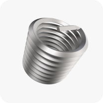
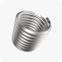
With the hole drilled, countersunk, tapped, and gaged, you’re now ready to install the KATO® wire thread insert. Use the KATO® installation tool to install the insert. The tool ensures that the insert is seated at the correct depth, which is crucial for maintaining thread integrity and performance. Depending on whether the hole is countersunk, the insert should be set 3/4 to 1-1/2 turns below the surface (with countersink) or 1/4 to 1/2 turns (without countersink). For tangless inserts, the installation is complete once the insert is at the correct depth.
If you’re installing a tanged insert, after setting the insert at the correct depth, use the KATO Tang Break-off Tool to remove the tang. This step is necessary to ensure that the bolt or screw fully engages the locking coils of the insert. In blind holes, make sure to remove the broken tang from the bottom of the hole to prevent any interference with the bolt or screw.
Get perfect joint performance with KATO® Advanex
Installing KATO® wire thread inserts is a precise process that, when done correctly, significantly enhances the strength, durability and reliability of threaded joints. By following these steps carefully and paying attention to critical details, you can ensure that your installations are both effective and long-lasting. Whether you’re working on aerospace components or other demanding engineering projects, mastering the installation of KATO® wire thread inserts will help you achieve superior results every time.
To find out more about our products or to get additional pricing information, contact a member of our team today.






.jpg?width=352&name=Ellipta%20sieving%20into%20carousel%20(1).jpg)
